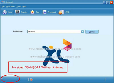
Previously I had to modify the 2.4 GHz antenna to Support CDMA 1900MHz with pcb induction system (PCB induction of the search results there are many who use it too). 3G/HSDPA Coverage Area Since not all complete in every area. (including my area which is out of range) can not access 3G/HSDPA services . first find out the distance of closest area we are already 3G/HSDPA coverage service area and hopefully we can know the position of 3G/HSDPA base stations .If information is obtained we will catch the signal 3G/HSDPA using a Yagi antenna 20 Element pointing directed to the BTS.
Materials and equipment needed include:
1.Bor
2.Solder
3.Glue
4.Jig saw
5.cutting pliers
6.Aluminum pipe box w = 12mm H = 20mm L = 110mm
7.Electrical cable diameter copper wire 1.95mm
8.Line telephone box
9.Pcb
10.Antenna cable RG-6 length 15m-20m
11.Hot gun glue
12.Antenna clamp
The steps of manufacture as follows:
1.materials required

Telephone line cable box

¢ copper electrical wires 1.95 mm

Plain pcb to taste

Aluminum pipe box w = 12mm H = 20mm L = 110mm
2. From the above ingredients if you want the antenna to work in frequency 2150 MHz is obtained using the following calculation Yagi Calculator Software Version 2.6.5
VK5DJ’s YAGI CALCULATOR
Yagi design frequency =2150.00 MHz
Wavelength =139 mm
Parasitic elements contacting a square section metal boom 20.00 mm across.
Folded dipole fully insulated from boom
Director/reflector diam =1.95 mm
Radiator diam =1.95 mm
REFLECTOR
83 mm long at boom position = 30 mm (IT = 31.5 mm)
RADIATOR
Single dipole 64 mm tip to tip, spaced 28 mm from reflector at boom posn 58 mm (IT = 22.0 mm)
Folded dipole 66 mm tip to tip, spaced 28 mm from reflector at boom posn 58 mm (IT = 23.0 mm)

COMMENTS
The abbreviation “IT” means “Insert To”, it is the construction distance from the element tip to the edge of the boom for through boom mounting
Spacings measured centre to centre from previous element
Tolerance for element lengths is +/- 0 mm
Boom position is the mounting point for each element as measured from the rear of the boom and includes the 30 mm overhang.The total boom length is 1007 mm including two overhangs of 30 mm
The beam’s estimated 3dB beamwidth is 26 deg
A half wave 4:1 balun uses 0.75 velocity factor RG-6 (foam PE) and is 52 mm long plus leads
FOLDED DIPOLE CONSTRUCTION
Measurements are taken from the inside of bends
Folded dipole length measured tip to tip = 66mm
Total rod length =156mm
Centre of rod=78mm
Distance BC=CD=18mm
Distance HI=GF=13mm
Distance HA=GE=36mm
Distance HB=GD=60mm
Distance HC=GC=78mm
Gap at HG=10mm
Bend diameter BI=DF=30mm

If the folded dipole is Considered as a flat plane (see ARRL Antenna Handbook) then its resonant frequency is less than the flat plane algorithm's range of 10:1

3.The calculation obtained as above then peel and cut the electric cable according to the size of the copper wire above

4. drill pipe as a boom box with distance reflector, RADIATOR AND DIRECTOR mentioned above to be reckoned antenna
5.Cuting pcb the size of the entry into the cable box telephone. exfoliate the center line a distance of 10mm folded dipole. gap distance corresponding holes on the edges give

6. Create RADIATOR Folded dipole according to the size and solder on the PCB that has been made

7. materials are assembled now ready

8.Assembly 20 elements to the boom in order of size on the calculation and the key elements with small pieces of the outer layer of the cable. And glue so does not change the size of the height of the boom.
9.Make antenna balun of RG-6 cable and solder on a folded dipole RADIATOR

10.Assembly telephone line box at the bottom of the Boom. And screw in securely
11.Replace the existing pcb balun Radiator and telephone line in the box was then screw in the hole pcb. Next soldering the antenna cable as directed on Contruction balun


12.Close with cover telephone line cable box that previously had made the hole to the right with the cable and the antenna radiator element

And glue with hot glue gun or glue in the holes to be impervious to rain water
13.Making 3G/HSDPA Yagi antenna has been completed and can be linked with the usb modem through a pigtail cable connection which I have described previously How to make your own pigtail cable


14.Instalation yagi antenna on the pole and navigate to the base stations your area of covered 3G/HSDPA.IF certainly want to get maximum results try any antenna is not obstructed. Thus the addition of the signal obtained maximal.Connect antenna cable to the usb modem 3G/HSDPA via cable pigtail or PCB induction
Pict Result tested:
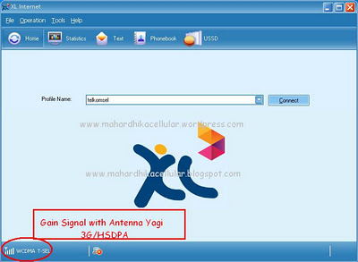


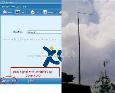
Antenna mast height of approximately 5 meter.And pointing toward the corner of the search base stations are very influential when the shear signal drops to 30 degrees while pointing direction slowly so that it can be the result of maximal

www.mahardhikacellular.blogspot.com
Materials and equipment needed include:
1.Bor
2.Solder
3.Glue
4.Jig saw
5.cutting pliers
6.Aluminum pipe box w = 12mm H = 20mm L = 110mm
7.Electrical cable diameter copper wire 1.95mm
8.Line telephone box
9.Pcb
10.Antenna cable RG-6 length 15m-20m
11.Hot gun glue
12.Antenna clamp
The steps of manufacture as follows:
1.materials required
Telephone line cable box
¢ copper electrical wires 1.95 mm
Plain pcb to taste
Aluminum pipe box w = 12mm H = 20mm L = 110mm
2. From the above ingredients if you want the antenna to work in frequency 2150 MHz is obtained using the following calculation Yagi Calculator Software Version 2.6.5
VK5DJ’s YAGI CALCULATOR
Yagi design frequency =2150.00 MHz
Wavelength =139 mm
Parasitic elements contacting a square section metal boom 20.00 mm across.
Folded dipole fully insulated from boom
Director/reflector diam =1.95 mm
Radiator diam =1.95 mm
REFLECTOR
83 mm long at boom position = 30 mm (IT = 31.5 mm)
RADIATOR
Single dipole 64 mm tip to tip, spaced 28 mm from reflector at boom posn 58 mm (IT = 22.0 mm)
Folded dipole 66 mm tip to tip, spaced 28 mm from reflector at boom posn 58 mm (IT = 23.0 mm)
COMMENTS
The abbreviation “IT” means “Insert To”, it is the construction distance from the element tip to the edge of the boom for through boom mounting
Spacings measured centre to centre from previous element
Tolerance for element lengths is +/- 0 mm
Boom position is the mounting point for each element as measured from the rear of the boom and includes the 30 mm overhang.The total boom length is 1007 mm including two overhangs of 30 mm
The beam’s estimated 3dB beamwidth is 26 deg
A half wave 4:1 balun uses 0.75 velocity factor RG-6 (foam PE) and is 52 mm long plus leads
FOLDED DIPOLE CONSTRUCTION
Measurements are taken from the inside of bends
Folded dipole length measured tip to tip = 66mm
Total rod length =156mm
Centre of rod=78mm
Distance BC=CD=18mm
Distance HI=GF=13mm
Distance HA=GE=36mm
Distance HB=GD=60mm
Distance HC=GC=78mm
Gap at HG=10mm
Bend diameter BI=DF=30mm
If the folded dipole is Considered as a flat plane (see ARRL Antenna Handbook) then its resonant frequency is less than the flat plane algorithm's range of 10:1
3.The calculation obtained as above then peel and cut the electric cable according to the size of the copper wire above
4. drill pipe as a boom box with distance reflector, RADIATOR AND DIRECTOR mentioned above to be reckoned antenna
5.Cuting pcb the size of the entry into the cable box telephone. exfoliate the center line a distance of 10mm folded dipole. gap distance corresponding holes on the edges give
6. Create RADIATOR Folded dipole according to the size and solder on the PCB that has been made
7. materials are assembled now ready
8.Assembly 20 elements to the boom in order of size on the calculation and the key elements with small pieces of the outer layer of the cable. And glue so does not change the size of the height of the boom.
9.Make antenna balun of RG-6 cable and solder on a folded dipole RADIATOR
10.Assembly telephone line box at the bottom of the Boom. And screw in securely
11.Replace the existing pcb balun Radiator and telephone line in the box was then screw in the hole pcb. Next soldering the antenna cable as directed on Contruction balun
12.Close with cover telephone line cable box that previously had made the hole to the right with the cable and the antenna radiator element
And glue with hot glue gun or glue in the holes to be impervious to rain water
13.Making 3G/HSDPA Yagi antenna has been completed and can be linked with the usb modem through a pigtail cable connection which I have described previously How to make your own pigtail cable
14.Instalation yagi antenna on the pole and navigate to the base stations your area of covered 3G/HSDPA.IF certainly want to get maximum results try any antenna is not obstructed. Thus the addition of the signal obtained maximal.Connect antenna cable to the usb modem 3G/HSDPA via cable pigtail or PCB induction
Pict Result tested:


Antenna mast height of approximately 5 meter.And pointing toward the corner of the search base stations are very influential when the shear signal drops to 30 degrees while pointing direction slowly so that it can be the result of maximal
GOOD USEFUL
Translator By Google


Created By:

Heru DA..
Heru DA..
Admin :
www.mahardhikacellular.wordpress.com www.mahardhikacellular.blogspot.com

ini bisa buat CDMA jg gak pak? buat nyari sinyal evdo gt.
ReplyDelete@up
ReplyDeletebisa saja tinggal sesuaikan frekuensinya jadi 1900mhz pada software perhitungan antennanya
This comment has been removed by a blog administrator.
ReplyDeletecan u please post the result of your works yagi antenna in your broadband
ReplyDeletePlease see pict result tested now
DeleteThanks from Morocco
ReplyDeleteGan bisa kasih saran gk untuk masalah pembuatan RADIATOR Folded dipole g bisa melengkung?sama ss nomer 9 itu kabel serabut yang putih di jadiin satu apa gmn?
ReplyDeletekalau menggunakan bahan seperti diatas radiator kan mudah membuat melengkungnya buatnya pakai pakai jig dengan paku pada papan/triplek,utk kabel serabut digabung jadi satu dan di hubungkan ke serabut kabel antenanya
DeleteAntena grid bisa di buat gini ga bang?
ReplyDeleteKalo bisa, gimana caranya bang?
Mohon bantuannya bang, trimakasih..
bisa gak dipadu dengan antena starbolic? klu bisa apa titik fokus pada starbolic tepat pada radiator(balun)?
ReplyDeleteDinung....
ReplyDeletegleek....
DeleteHer,, driven antena grid wifi buat akses point (untuk transmiter yg sip gimana?? )
ReplyDeleteThis comment has been removed by a blog administrator.
ReplyDelete